This project is occurring on someone else’s air-to-air heat pump. They very kindly (and very very foolishly) let me take it apart and faff around with it. As I have to travel to it, each visit is a learning process. So, I have an idea in my mind, only to find out that it doesn’t work or is nowhere near as easy as I had hoped.
It’s a bit like giving someone else a lecture on how to do something, mostly when you give unsolicited advice you don’t have a chance to find out your idea is terrible. Unfortunately, I have been on the receiving end of this terrible advice and taking it. So here is my documentation of failure – attempting to get reliable refrigerant temps off an air to air heat-pump.
Why I’m doing this
Refrigerant condensing temps relate to the COP. I want to know COP varies with fan speed. But also this is a secondary measurement for my mass flow COP estimates, it is always good practice have more than one point of failure. Many people achieve this secondary point of failure by getting married as it allows you to blame your other half.
Part 1. There is no space.
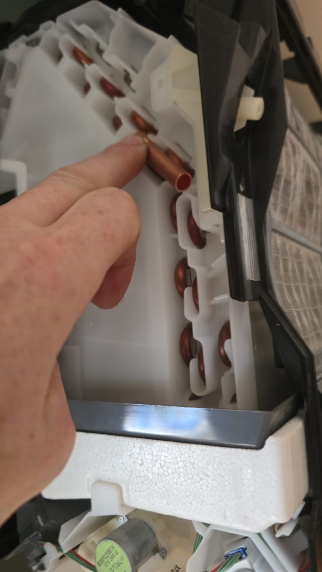
I have been struggling to get reliable readings from my sensors on the condenser and evaporator coils. One issue is that I’m putting sensors on a live unit, which—as you can see from the picture below—isn’t suitable for brazing (lots of plastic and refrigerant).
I can hear some people asking “Are you F-GAS”. My answer to that is don’t ask questions that I don’t want to answer. Plus I’m not doing any actual extraction of refrigerants.
Anyway. what began as a bit of a ‘bodge’ and a “hope this will work” is turning into a bit of an obsession. My first attempt was to place a DS18B20 inside an 8mm copper pipe – thanks to City Plumbing who sold me a single meter of it of it.
This might have been the shortest length of 8mm copper pipe they have ever sold. I should probably get some type of reward, maybe a display. In the store they asked me what I wanted it for; I paused briefly, then said, “It’s a bit complicated.” I thought they probably didn’t want to hear the entire story. I didn’t think I could give them a plausible answer.
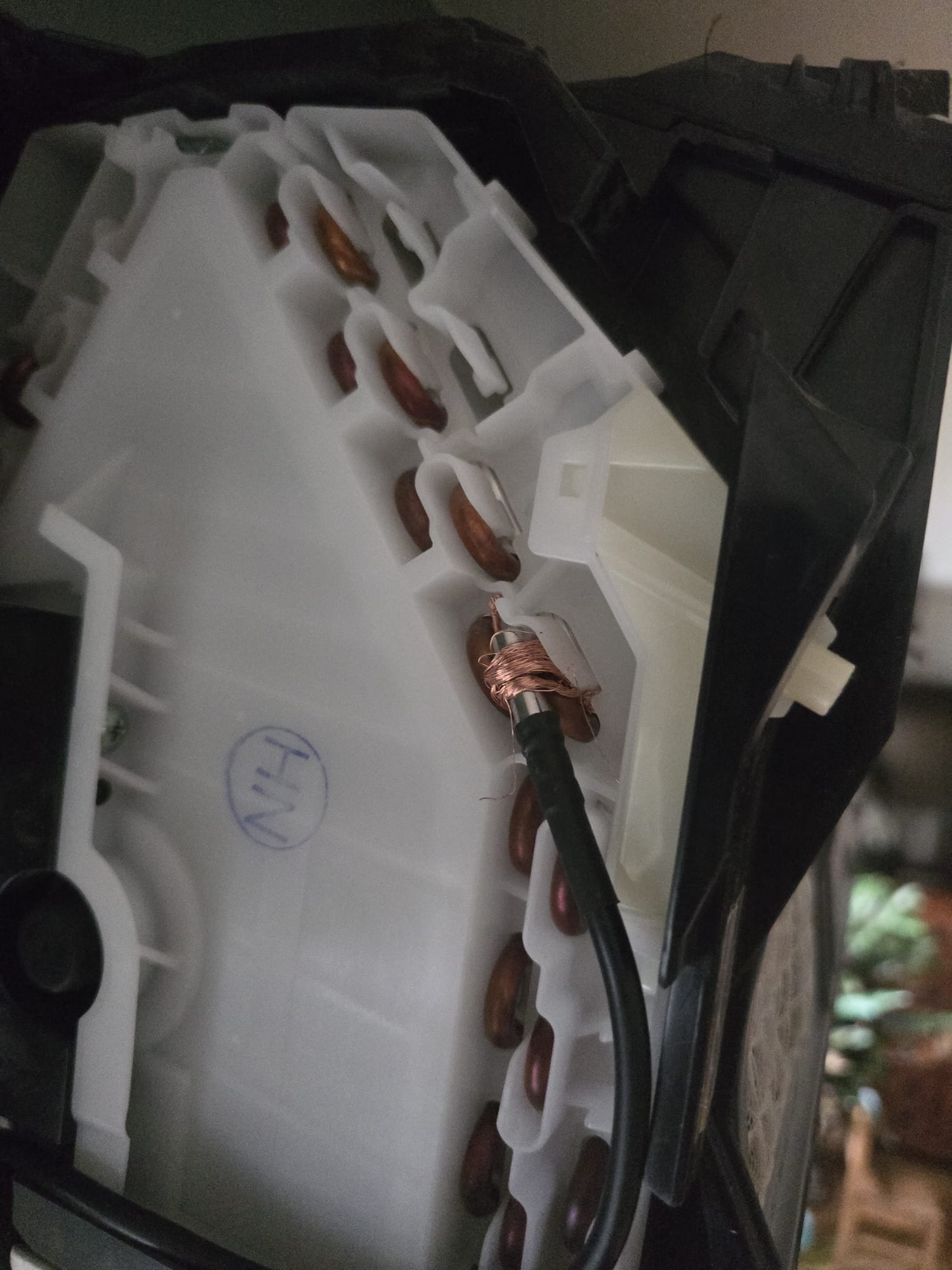
Below is my attempt at wrapping this copper pipe to the copper evaporator coils (yes, HVAC installers, we are evaporating, and I’ll be in my cold hard grave before I call the external unit a condenser).
The connection was good and tight, and it was wrapped and insulated. But I didn’t get readings off it which I was convinced of. Copper is very conductive, stupidly so, you can test this by holding a piece of copper and heating it up with a soldering iron, you will quickly burn yourself. If you do the same thing with cast iron you will barely feel a tinge of heat.

The internal units presented even more of a challenge. As you can see, there is essentially no space to work. I say “no space,” but I can quantify that: there is exactly 0.35mm of space around some of the condenser end loops. Which equates to fuck all.
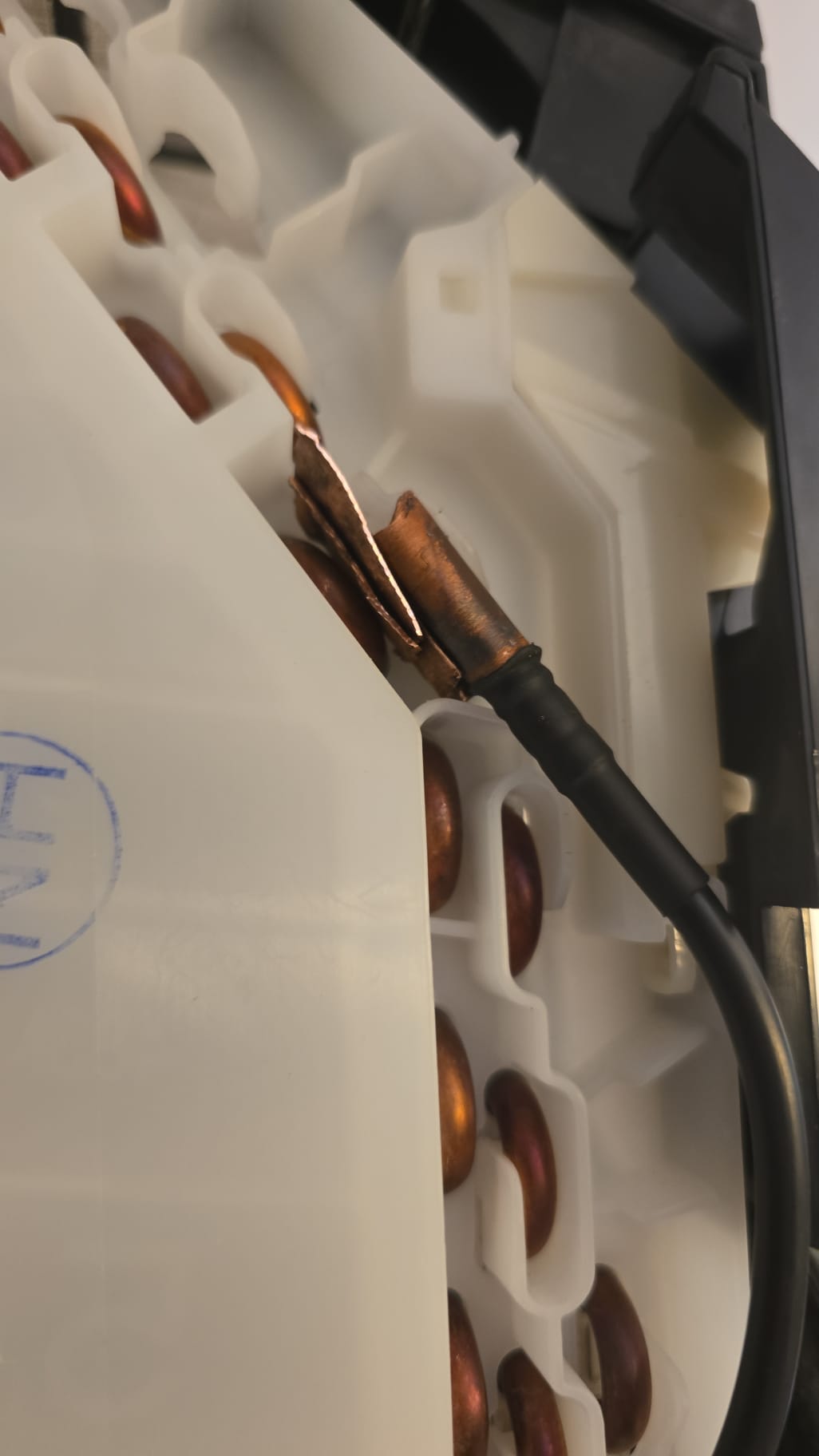
Some loops have a bit more space, which is how I managed to badly attach the sensor to them. By this point, I had exhausted my previous hopes of how I might attach my sensor. The space constraints were far more severe than I had hoped. I was just giving it a go to see what would happen.
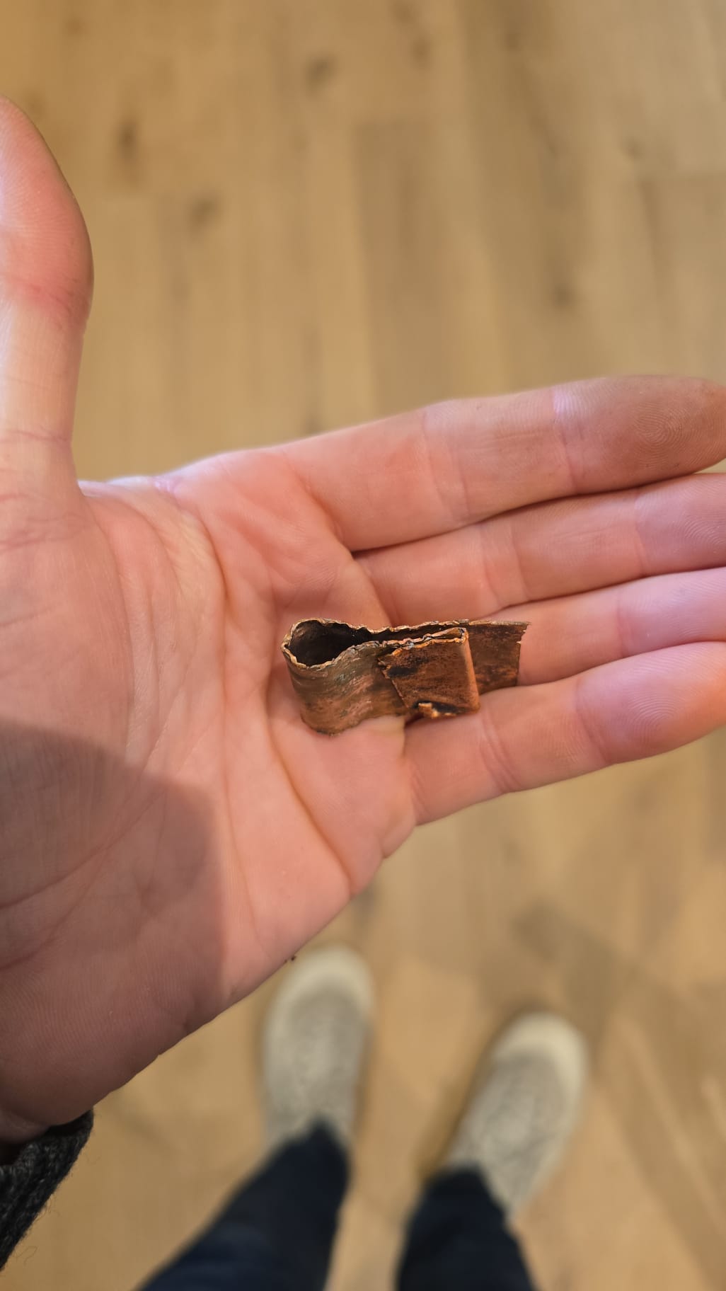
After this, I went home and set about trying to fabricate a little clamp. The only copper I had was the one meter of 8mm diameter copper pipe, which I had to cut in half and hammer flat. This is objectively terrible – a bad workman blames his tools – but without a hard, flat surface to hammer onto, I don’t actually have any tools to blame. So I can only blame myself and I do so every time I look at this picture.
Anyway, I tried it, but I had once again failed to appreciate how excruciatingly tight the heat exchanger is. I sort of wedged it in as a bodge to see what it would do once again. It was wrapped and insulated again too. As I expected it failed. I know it failed because my temperature reading for the air leaving the unit was always above the sensor temp. So I at least had a way to know whether my sensor was giving a good reading.
Part 2 John Cantor sends me some bits
John Cantor kindly sent me over a couple of things: some spare copper sheet that he had been making solar panels out of in the 1980s, a little mount that he had made, and some more small TO92 sensors. The hope was that these additions would provide better readings.
I started with some relatively simple methods, such as wrapping the TO92 sensor in 0.35mm copper sheet to try and hold them near the coil, then insulating them. I didn’t actually want to use this approach, it is just that there was so little space I didn’t have a better plan at the time.
I didn’t have high hopes for this method and didn’t get great results. Part of this was due to the sensor twisting—which I hadn’t seen until I looked at the photos later—but it was also likely due to a lack of thermal paste.
For the outside unit, he had brazed a little mount together. I don’t have a picture of this installed, but once again, I didn’t find my readings trustworthy. I now suspect that adding some thermal paste might assist in improving the readings. I will also get some liquid rubber to seal the copper components and the sensors from the external air before adding insulation.
Part 3 Starting my own foundry.
My girlfriend was out for the weekend, so I thought it would be the perfect time for me to begin casting my own metal parts on the hob. In this picture, you can see the 8mm copper pipe that an encapsulated DS18B20 can slide into.
Hamid Salimi of Daikin kindly organised some of the 6mm end loops to be sent out to me, which I put to good use. The aluminium foil was to stop the 6mm end loops from sticking to the solder it was there to cast around. As you can see, I made a little casting bath (this is a new technical term I have invented) from copper sheet. All I did then was chop up solder, pop it in the casting bath, and get it hot. It only took me a couple of goes to produce something that sort of worked. I say chop up, I poked it into the gaps I wanted to fill and watched it fall melt off the reel.
I didn’t have the right tools for cleanup—no Dremel to polish—so I had to live with the rustic aesthetic that the casting bath produced.
No, it’s not crack, I promise!

I now have a DS18B20 sensor in one of these mounts, which is working. However, I did have an issue when installing. It turns out the radii of the curves of the Daikin air-to-air unit are not the same as my Mitsubishi unit. Which, of course, means that the entire curve isn’t in contact with the surface – sort of defeating the point.
But we live and learn. The next step will be to take a mould of the Mitsubishi unit’s curve and fit some 6mm pipe to it. Then, I’ll try making a cast for that.
All in all, this has been quite a good learning curve (get it). I still need to get my own air-to-air unit so I can iterate faster.
This new cast sensor with thermal paste warms up faster than my air temp sensor below the unit—which is the right behaviour. I just need to fit a lot more of them and iterate on the design a little. But I have a cunning plan… TBC
